Low Side switching and High Side Switching for Arduino/ microcontroller based applications


What is High/ Low Side Switching

There is no need to explain, following diagram explains what High Side Switching and what Low Side Switching is,


High Side vs Low Side Switching

High/Low Side Switching Using BJTs. (Bipolar Junction Transistors)


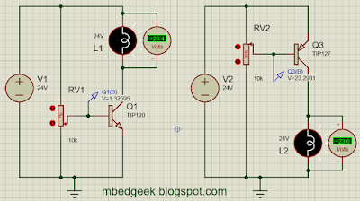
Since microcontroller applications are either 5V or 3.3V operated it is much easier to do the low side switching in a common ground situation. Lets take an application of switching a 24V Lamp using a transistor.

Low Side and High Side Switching concept
Low Side and High Side Switching with transistors concept


  • Left diagram  of Low side switching where switching voltages are 0 V(Off) and 1.3 V(On) 
  • Right diagram of high side switching where switching voltages are 24 V(Off) and 23.3 V (On)
*note : Variable resistors are used to identify the switching voltages of the BJTs/MOSFETs.

So it is clear that we can easily switch low side using microcontrollers where the voltage is in the range of 0-3.3/5V. However there are occasions where we do not have the luxury of low side switching.
  • when there is an application with common ground (ex : RGB strip with common ground) we cannot switch the low side. (ground)
  • When we want to isolate the positive side from the load (ex: in Automobiles)
  • When we need to isolate the positive due to safety concerns.

Lets design a circuit for High Side Switching.

High Side Switching using Transistors


This way we can control the lamp with a lower voltage. (About 1.2 V) Now we can add a current limiting resistor and replace the variable resistor with microcontroller/ Arduino output as below.


High Side Switching using Transistors for microcontrollers


High/Low Side Switching Using MOSFETs


We'll see how we can do the switching using MOSFETs too. For Low side switching, we'll use a logic level N channel MOSFET for the convenience. Logic Level MOSFETs operate within the range of 0-3.3/5 V range where we can easily operate using a microcontroller directly.


Low side switching with MOSFETs concept

See the operating Voltage (Vgs) is 3.84 V where it can be operated using even an Arduino. It is also important to note that MOSFETs are voltage operated devices where transistors are current operated.
Below diagram shows how it can be directly operated using an output pin of a microcontroller.
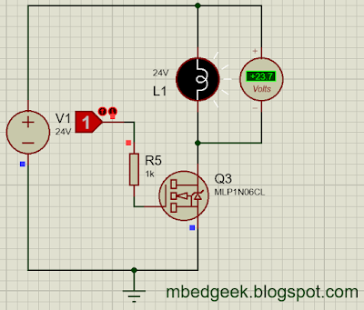

Low side switching with MOSFETs for microcontrollers

note : if the Gate pin of the MOSFET is too sensitive (operates due noise or ESD) you can pull down the pin using a resistor. However with the microcontroller pull down there may not be such a requirement.

Easiest way to switch high side using MOSFET is by using a P-Channel MOSFET


High Side Switching Using P-Channel MOSFET

There is a small disadvantage over using this method which is, normally P-channel MOSFETs have higher Drain to Source On-State Resistance compared to N-channel MOSFETs. Therefore it would be more efficient and convenient (in heat sink sizing etc) if we can switch the high side by N-Channel MOSFETs. There are couple of solutions for this issue. We'll discuss about Bootstrap circuits and high side MOSFET gate drivers. 

In the following video, 0033mer explains the bootstrap circuit really well and it is worth watching rather than reading.


Lets see how can we use MOSFETS with a power MOSFET driver. In the following example, it can switch both high side and low side. MOSFET driver used is , IR2101. (refer the linked datasheet for more information)


High and Low Side Switching with MOSFET Driver

*Note : It is always really important to use Freewheeling/Flyback diodes with inductive loads to protect BJT/MOSFETS.


Microcontrollers Vs Microprocessors

Let's compare Microcontrollers and Microprocessors

Microprocessor Vs Microcontroller
Microprocessors
  1. Some microcontrollers contain cache memory, however they require an external memory to function.
  2. Are not capable in storing programs where firmware has to be loaded during the boot process.
  3. Applications are mostly Software development, Gaming, Web Applications, Documentation, AI algorithms and Image Processing etc.
  4. Used in: 
    • Personal Computers
    • Mobile Phones
    • Laptops
    • Tablets

Some Example Microprocessors

  • AMD (Athlon 1400C, FX-8170)
  • Intel (XEON 7110M, Core i7-7970X)


Microcontrollers

  1. Are typically programmed to do a specific task/tasks and need to be programmed
  2. Some microcontrollers may have an internal clock.
  3. Microcontrollers contains I/O buses like UART, I2C, SPI etc.
  4. Microcontrollers contains inputs, Outputs, ADC, PWM etc.
  5. Used in : 
    • Applications that contains Inputs (Sensors) and Outputs to do a programmed task.
    • Data logging/processing devices which handles a lower amount of data and lower processing
      • ex : Washing Machines, Toys, Robots, Instrumentation devices, Automobiles etc.


Some Example Microcontrollers

  • Microchip PIC (16F877A, 18F452)
  • Atmel AVR (ATmega328P, ATmega32A)


When and Where we can use resistors to step down voltages


We've already discussed some points on Buck Converters, Linear Regulators and LDOs. (Linear Drop Out Regulators) Reading following posts will give you little more knowledge on other options to step down the voltage.

  1. Voltage Regulators
  2. LM2596 Buck Converter Vs LM7805 Linear Voltage Regulator
  3. How to make a dual power supply
  4. DIY Power Supply from a Computer Power Supply

When it comes to stepping down/reducing voltage first thing that may come to your mind would be resistors. True, there are occasions that we can use resistors, And there are occasions that we can't. Lets have a look at what they are. Following example is from my previous example of Arduino Blink.


"Calculating the current limiting resistor value

Generally we put 270 Ohms or 330 Ohms resistors in series when selecting a current limiting resistor. However most people does not have an idea about selecting the resistor. Understanding the concept behind this will help you to select current limiting resistors for different scenarios. Also it is really important to verify that heat emission must be lesser than the wattage of the resistor


Current Limiting Resistor
Current Limiting Resistor, Arduino Blink


{In a series circuit, current through each component is same and, the voltage across the circuit is the sum of voltages across each component.}

V1 = 2.2V (assuming 2.2V rated LED)

Therefore,
V2 = 2.8V  (Above equation, Kirchhoff's Voltage Law)
Applying Ohms Law for the R resistor,


Since 280 Ohms resistors are not available we can select either 270 Ohms or 330 Ohms resistors. However this value can be changed depending on the current LED draws.(depend on the colour, size etc of the LED)"


Lets see the power dissipation calculation in Resistor and the LED,
Power dissipation Calculation
We can simulate the result using Proteus. (There is a very small difference in the values due to LED current I've assumed in above calculation)


Power dissipation Simulation
  • If we take the above example efficiency is only about 44% {=18.7/(18.7+23.8)}
  • And resistor must have the capability to dissipate the wattage of 23.8 mW


Lets take another application for the below specification,


  • Supply Voltage = 24 V
  • Lamp Voltage = 12 V 
  • Lamp Rated Current = 6 Ohms

To reduce the voltage resistor should also be 6 Ohms,


Resistor Voltage Reduction

As per this circuit,

  • Efficiency is only 50%
  • Since resistor should have the capability to dissipate 23.3 W it has to be a considerably large one.

Conclusion
  • Resistor Voltage reduction options are not efficient.
  • If the power dissipation is high (Load draws more current/Voltage drop is high) resistors has to be larger.

Though we have not proved, following rules also has to be considered

  • If the supply voltage changes, output voltage also will change.
  • If the load current is not constant, output voltage also varies.
Linear Regulators, Buck Converters and LDOs are much more better than resistor voltage reducing circuits. However the main disadvantage of them compared to resistors is that they may generate harmonics/noises due to high speed switching. (Non-Linearity) Generally resistors are good only when the supply voltage is constant, Load current is constant, Load requires a very minimum current and the voltage drop required is very low.


How to operate relays using Arduino ?


Why we cannot operate relays directly using Arduino or any other microcontroller ?

Lets take a look at what Arduino Uno datasheet says,


Arduino Specifications Datasheet
Arduino Specifications Datasheet (Image Courtesy, farnell.com)

Since Arduino Uno consists with ATmega328P microcontroller, we'll have a look at its data sheet too.


ATmega328P Specifications Datasheet
ATmega328P Specifications Datasheet (Image Courtesy, microchip/atmel)

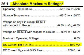
Also Arduino.cc suggests DC current per I/O pin to be 20mA. So we cannot design anything for 40mA as it is the absolute maximum. Normally a small relay may consume a current starting from 20mA to 60 mA. However even if the current was enough, it can damage the microcontroller due to flyback voltage spikes that comes due to inductive load of the relay. Therefore even if it works, never connect a relay directly with a microcontroller.


Wrong connection of relay with microcontroller
Wrong connection of relay with microcontroller 

So there are few options we can use to connect relays, We'll go through couple of solutions.

Connecting relay using a transistor,


In this method, relay is not electrically isolated from the microcontroller. A freewheeling diode is recommended for the protection of the transistor. Output pin has to be high in order to power the relay coil.

Connecting relay to a microcontroller using a transistor
Connecting relay to a microcontroller using a transistor 

Operate relay using a transistor
Operate relay using a transistor 

Connecting relay using Darlington arrays


In this method also relay is not electrically isolated from the microcontroller. However this will be one of the best option when we have to connect a series of relays for a microcontroller. Since this darlington array I've selected has inbuilt freewheeling diodes, there is no need to add flyback protection for this.


Connecting relay to a microcontroller using a Darlington Array
Connecting relay to a microcontroller using a Darlington Array

Operate relay using a Darlington Array

Connect Relays using Opto-couplers


Even though this circuit is little more expensive than the previous methods, it has a great advantage over previous methods. If your microcontroller circuit is delicate, susceptible to noise or sensitive, optocouplers in this circuit isolates the signal side from relay electrically. (connected optically) 

Lets see how we connect it if we choose to switch the ground connection. In this method output of 0 V will operate the relay. Advantage of this method is that we can choose the supply voltage of the microcontroller/ separate voltage source to operate the relay.

Connecting relay to a microcontroller using Optocouplers, Low Side
Connecting relay to a microcontroller using Opto-couplers, Low Side


Also we can switch the high side of the Opto-coupler where relay will operate when output signal is high. Diagram below highlights the electrical isolation too.


Connecting relay to a microcontroller using Optocouplers, High Side
Connecting relay to a microcontroller using Opto-couplers, High Side

Operate relay using an Opto-Coupler


ULN2003A Darlington array Based DC Motor Driver


DC motor control using ULN2003A Darlington Array

In terms of DC motor controlling ULN2003A will not be the great option as it does not support direction change of the motor. However there are few other advantages of the driver.

  • 500mA Rated Collector Current
  • High Voltage Outputs (50V)
  • CMOS, TTL compatibility
  • Inclusion of Suppression Diodes (Easy to drive inductive loads like motors, relays etc)
  • Outputs can be connected in parallel to achieve higher current ratings

Lets see how it reacts on the input states. We'll use Proteus to simulate.

ULN2003A Simulation
ULN2003A Simulation

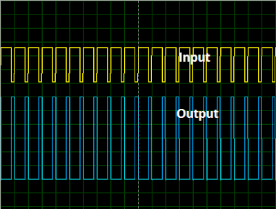
ULN2003A Simulation Oscilloscope Output


ULN2003A darlington array works like a not gate. Also note that we need to add load in order to simulate the output state.


Now lets see how we can use it as a DC Motor Driver

For this exercise also we can use Proteus to simulate.

ULN2003A DC Motor Control


Output from the Oscilloscope is same as the previous one above. Also note that I had to pulldown the input pin due to Switch resistance, Input impedance and the supply frequency. In practical, it may not be necessary but, better to put a resistor. Also it will even help to reduce noise due to human touch and EMI etc. Addition of a smoothing capacitor for the power source will make it more robust if power source is not a battery.

Most importantly this motor driver is not an ideal solution for many cases as it cannot operate bi-directional. (Cannot change the direction of the motor) So there are better options like L298, L293 etc.