What is High/ Low Side Switching
There is no need to explain, following diagram explains what High Side Switching and what Low Side Switching is,
 |
| High Side vs Low Side Switching |
High/Low Side Switching Using BJTs. (Bipolar Junction Transistors)
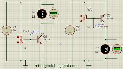
Since microcontroller applications are either 5V or 3.3V operated it is much easier to do the low side switching in a common ground situation. Lets take an application of switching a 24V Lamp using a transistor.
 |
| Low Side and High Side Switching with transistors concept |
- Left diagram of Low side switching where switching voltages are 0 V(Off) and 1.3 V(On)
- Right diagram of high side switching where switching voltages are 24 V(Off) and 23.3 V (On)
So it is clear that we can easily switch low side using microcontrollers where the voltage is in the range of 0-3.3/5V. However there are occasions where we do not have the luxury of low side switching.
- when there is an application with common ground (ex : RGB strip with common ground) we cannot switch the low side. (ground)
- When we want to isolate the positive side from the load (ex: in Automobiles)
- When we need to isolate the positive due to safety concerns.
Lets design a circuit for High Side Switching.
This way we can control the lamp with a lower voltage. (About 1.2 V) Now we can add a current limiting resistor and replace the variable resistor with microcontroller/ Arduino output as below.
 |
| High Side Switching using Transistors for microcontrollers |
High/Low Side Switching Using MOSFETs
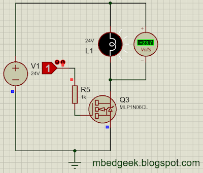
We'll see how we can do the switching using MOSFETs too. For Low side switching, we'll use a logic level N channel MOSFET for the convenience. Logic Level MOSFETs operate within the range of 0-3.3/5 V range where we can easily operate using a microcontroller directly.
 |
| Low side switching with MOSFETs concept |
See the operating Voltage (Vgs) is 3.84 V where it can be operated using even an Arduino. It is also important to note that MOSFETs are voltage operated devices where transistors are current operated.
Below diagram shows how it can be directly operated using an output pin of a microcontroller.
 |
| Low side switching with MOSFETs for microcontrollers |
note : if the Gate pin of the MOSFET is too sensitive (operates due noise or ESD) you can pull down the pin using a resistor. However with the microcontroller pull down there may not be such a requirement.
Easiest way to switch high side using MOSFET is by using a P-Channel MOSFET.
 |
| High Side Switching Using P-Channel MOSFET |
In the following video, 0033mer explains the bootstrap circuit really well and it is worth watching rather than reading.
Lets see how can we use MOSFETS with a power MOSFET driver. In the following example, it can switch both high side and low side. MOSFET driver used is , IR2101. (refer the linked datasheet for more information)
 |
| High and Low Side Switching with MOSFET Driver |
*Note : It is always really important to use Freewheeling/Flyback diodes with inductive loads to protect BJT/MOSFETS.
