Key Topics : What is I2C, I2C Scanner, Arduino Wire, TWI
Before going into I2C Scanner, Lets have a some understanding of what I2C communication is.
I2C communication is a very easy to use synchronous serial communication protocol. It supports multiple masters and multiple slaves with only two wires ! Also important to note that we can connect any number of masters and up to 1008 slave devices to an I2C network. (But in our case, since we use 7 Bit addresses we can theoretically put only 127 slaves, that also may come down depending on the capacitance on the I2C Bus.) Compared to SPI (Serial Peripheral Interface), it has a lower data transfer rate. Pull up resistors are required when you connect more than two devices to the network. I2C bus drives can pull signal lines to ground but they are not capable of driving it to high. Therefore Pull Up resistors are vital. General rule of thumb is to start from 4.7k Ohms resistors and bring it down depending on the length and the connected devices of the system. When using the wire library (for I2C in Arduino) it activates internal pull-up resistors (20k-150k, depending on the pin and the board model) and Mega 2560 board has on board pull up resistors (10k).
 |
| An I2C network |
I2C, TWI and WIRE
Since I2C is a trademark for Phillips Atmel and other companies created an identical system called TWI (Two Wire Interface) which is very much identical to I2C. In Arduino Wire library is used communicate with I2C/TWI communication devices. Some of the commonly available I2C devices are listed below.
 |
| Real Time Clock |
 |
| AD-DA Module |
I2C OLED
 |
| I2C LCD module |
 |
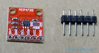
| MCP4725 I2C DAC |
What are the dedicated I2C pins in Arduino Boards
 |
| I2C connection pins in Arduino Uno |
 |
| I2C pins in different Arduino Boards |
It is important to have an idea about interfacing devices using I2C with different TTL logic levels.(3.3V and 5V) You can get a clear idea from here.
I2C Scanner
In most of the cases we see that people copy Arduino codes from internet and often say their codes are not working. Often manufacturers provide contingencies to change I2C adresses by doing minor hardware changes. (ex : removing/ adding resistors) When devices with I2C communication, first of all we need to check the I2C addresses of the devices. You can find the source code for I2C Scanner from official Arduino site. (https://playground.arduino.cc/Main/I2cScanner)
// This sketch tests the standard 7-bit addresses
// Devices with higher bit address might not be seen properly.


#include <Wire.h>


void setup()
{
  Wire.begin();

  Serial.begin(9600);
  while (!Serial);             // Leonardo: wait for serial monitor
  Serial.println("\nI2C Scanner");
}


void loop()
{
  byte error, address;
  int nDevices;

  Serial.println("Scanning...");

  nDevices = 0;
  for(address = 1; address < 127; address++ )
  {
    // The i2c_scanner uses the return value of
    // the Write.endTransmisstion to see if
    // a device did acknowledge to the address.
    Wire.beginTransmission(address);
    error = Wire.endTransmission();

    if (error == 0)
    {
      Serial.print("I2C device found at address 0x");
      if (address<16)
        Serial.print("0");
      Serial.print(address,HEX);
      Serial.println("  !");

      nDevices++;
    }
    else if (error==4)
    {
      Serial.print("Unknown error at address 0x");
      if (address<16)
        Serial.print("0");
      Serial.println(address,HEX);
    }
  }
  if (nDevices == 0)
    Serial.println("No I2C devices found\n");
  else
    Serial.println("done\n");

  delay(5000);           // wait 5 seconds for next scan
}
//Courtesy - arduino.cc
Here in this example we'll do the I2C Scanning for DS3231 based RTC (Real Time Clock)
 |
| I2C Scanner for RTC Schematic |
 |
| I2C Scanner for RTC Connections |
for this example there is no need to add pull-up resistors. After Uploading the code, open Serial Monitor. (Tools >> Serial Monitor) You'll get a message as follows.
 |
| I2C Scanner Output |
- 0x57 - AT24C32 EEPROM
- 0x68 - DS3231 RTC
However if you do not get the above results check the following,
- GND and Vcc Connevtion for your I2C device.
- SCL and SDA Connections Between Arduino and device.
- Baud-rate in code and serial monitor (9600 in this example)
- If you have more than one device you may need to add pull-up resistors.
- Sometimes your SCL and SDA cables may be too lengthy.
- Voltage level of the device (Some devices are 3.3V operated, I've posted a link above which explains how work with level shifters)
- This program supports only for devices with 7-bit addresses. Check your datasheet.
