Understanding the structure of Arduino Uno Board

Key Topics : Arduino Hardware Components, Arduino I/Os and other connections


Let's identify the main hardware components of an Arduino Uno Board


Arduino uno board hardware components
Arduino uno board hardware components (Photo credit : arduino.cc)

A : USB Type - B Connector (to talk with computer)
B : 2.1 mm DC Barrel Jack 
C : Voltage Regulator (6V-20V Limit)/(7V-12V Recomended)
D : Over Current Protection
E : 16MHz Regulator
F : ATmega16U2 (Programmed as a USB to TTL-Serial Converter, Note : Some boards had         options like CH340 IC and FTDI Converter)
G : Reset Switch
H : RX (Receive) and TX(Transmit) indicators for Serial Communication
I : ICSP -In Circuit Serial Programming (USB Interface)
J : LED connected to pin 13 
K : ATmega328 microcontroller
L : ICSP (for ATmega328P)
M : Power On LED


Arduino I/Os and other connections


Arduino Uno I/O connections
I/O and other connections
1 : SCL - Serial Clock (I2C Communication, Wire Communication in Atmel devices)
2 : SDA - Serial Data (I2C Communication, Wire Communication in Atmel devices)
3 : AREF - Analog Reference (Can be used to set the upper limit of Analog Inputs)
4 : GND
5 : General Inputs/Outputs ,Pins with ~ symbol supports PWM(Pulse Width Modulation Outputs
6 : TX : Transmit (Serial Communication)
7 : RX : Receive (Serial Communication
8 : Pins with ADC converters (Analog Inputs)
9 : Vin (Input power before regulator, Recommended Voltage is 7V-12V)
10 : 5V (5V bus of Arduino, Can be used to power up sensors, shields etc
11 : 3.3V (can be used to power 3.3V operated devices, sensors, modules etc)
12 : RESET : Reset Pin is useful in occasions where we use it as a programmer etc
13 : IOREF : Indicates the corresponding I/O voltage of the respective board ,(ex:Uno-5V, Due-3.3V)





Arduino Blink, Current Limiting Resistor, Blink without delay

Key Topics : Arduino Blink, Calculating the current limiting resistor value, Blink without delay


Arduino Blink Explained


This can be considered as your "Hello World" command in Arduino Journey. This comes as the default loaded code in Arduino. Digital 13 Pin is the LED Builtin pin for Arduino Uno and Mega. You can use any I/O pin including Analog inputs as per your preference.


Arduino Blink Connections


To access the code in Arduino IDE

Arduino IDE >> File >> Examples >> 01.Basics >> Blink


To use any pin as an Output


Digital pin 6 as the Output
Analog pin 2 as the Output


However when you have large no of I/Os and code is much more complex, It is easier to keep tracking of the Inputs and Outputs using variables. Therefore see the below example for using variables to hold the Input or Output pin number. This way you only need to change the pin no in Variable declaration to change it in entire code.


Calculating the current limiting resistor value

Generally we put 270 Ohms or 330 Ohms resistors in series when selecting a current limiting resistor. However most people does not have an idea about selecting the resistor. Understanding the concept behind this will help you to select current limiting resistors for different scenarios. Also it is really important to verify that heat emission is lesser than the wattage of the resistor. We will discuss that in a separate post.


Current Limiting Resistor, Arduino Blink


 {In a series circuit, current through each component is same and, the voltage across the circuit is the sum of voltages across each component.}

V1 = 2.2V (assuming 2.2V rated LED)

Therefore,
V2 = 2.8V  (Above equation, Kirchhoff's Voltage Law)
Applying Ohms Law for the R resistor,


Since 280 Ohms resistors are not available we can select either 270 Ohms or 330 Ohms resistors. However this value can be changed depending on the current LED draws.(depend on the colour, size etc of the LED)


Arduino Blink without delay

Disadvantage of Delay

During delays, Arduino will pause your program till the given delay and it will not execute other tasks. (Except Interrupts which we will be discussing later) However there are scenarios that we need to do more than one task at the same time.


Schematic for this example is same as the Arduino Blink (LED pin connected to the 13th pin/Or Builtin Pin) 


To understand this code you need to have some idea about the millis() function in Arduino. millis() return the time in milliseconds since the Arduino board powered up. 


You can download the code from below link.

Blink_Without_Delay_Code (mediafire)


/*This Arduino code will blink an LED without using delay function

  Reference : https://www.arduino.cc/reference/en/language/functions/time/millis/

  Coded by : Manjula Karunarathna
  Date : 22nd Nov 2018
*/

unsigned long PreviousTime = 0;             //To Save the last time we changed the state of LED
const unsigned long delayTime = 1000;       //Delay Time we need to Blink the LED
/*It is important to save the millis() value in an unsigned long variable since it returns the value in that format*/

volatile byte state = LOW;                  //To save the State of the LED           
int BlinkPin = 13;                          //Pin No to connect the LED

void setup() 
{ 
pinMode(BlinkPin, OUTPUT);                  //Declaring the Output
} 

void loop() 
{ 
unsigned long CurrentTime = millis();       //Obtain the current Time and Save it in a Variable

if (CurrentTime - PreviousTime >= delayTime)    //Check the time lapse since last change of state in LED
{
  state = !state;                               //If given time exceeded, Change the State
  digitalWrite(BlinkPin, state);
  PreviousTime = CurrentTime;                   //Save the time we changed the state
}
}


What are the Arduino Options

Key Topics : What is an Arduino, Different types of Arduino Boards, How to select an Arduino board

What is an Arduino

Arduino is an Open Source platform which supports for a range of microcontroller boards. Majority of the Arduino compatible boards use Atmel AVR microcontrollers*. However lately there has been some other types of microcontrollers that can be programmed through Arduino interface (Ex: ESP, STM32 ARM Cortex etc) Arduino has become popular due to few reasons like,
  1. Simplicity, easy to program 
  2. Lower hardware requirement (Programmers, Cables, Development boards etc.) 
  3. Open Source software, availability of resources, contribution from other developers etc. 
*Since Microchip Technology bought Atmel, AVR microcontrollers no longer comes as Atmel AVR microcontrollers.


Few commercially available Arduino boards

Arduino Uno rev3

Arduino Uno Rev3
Arduino Uno Rev3, Image courtesy : arduino.cc

Being an entry level and the most used board, this can be recommended as a robust Arduino board compared to other boards. Also there are lots of compatible shields for Arduino uno. (those shield that are compatible with uno are normally compatible with Arduino Mega 2560 also) Arduino UNO is based on the Atmel microcontroller ATmega328P.
  • Operating Voltage : 5V
  • Input Voltage : (6V - 20V) Limit / (7V – 12V) recommended
  • Digital I/O Pins : 14 (6 no of pins support PWM)
  • Analog Inputs Pins : 6 
  • DC current per I/O pin : 20mA
  • Flash Memory : 32 kB (0.5 kB used by Arduino bootloader)


Arduino Nano


Arduino Nano
Arduino Nano, Image courtesy : arduino.cc

Arduino Nano is a much smaller board similar to Arduino Uno. So the biggest advantage is that we can develop anything using Arduino Uno and replace with a Nano to make it compact at the end.
  • Operating Voltage : 5V
  • Input Voltage : (6V - 20V) Limit / (7V – 12V) recommended
  • Digital I/O Pins : 14 (6 no of pins support PWM
  • Analog Inputs Pins : 6
  • DC current per I/O pin : 40mA
  • Flash Memory : 32 kB (0.5 kB used by Arduino bootloader)
Arduino Mega 2560


ARDUINO MEGA 2560 REV3
Arduino Mega 2560, Image courtesy : arduino.cc

Arduino Mega 2560 is based on the ATmega 2560 microcontroller. Since Arduino Mega 2560 has much more I/Os, PWMs and ADCs it is much suitable for Robotic projects as well as projects related to 3D printers/ Cartesian robots etc.


  • Operating Voltage : 5V
  • Input Voltage : (6V - 20V) Limit / (7V – 12V) recommended
  • Digital I/O Pins : 54 (15 no of pins support PWM)
  • Analog Inputs Pins : 6
  • DC current per I/O pin : 20mA
  • Flash Memory : 256 kB (8 kB used by Arduino bootloader)
  • UARTs available : 04 Nos
Arduino Due


Arduino Due
Arduino Due, Image courtesy : arduino.cc

Arduino Due is based on a 32-bit ARM core microcontroller. ( Atmel SAM3X8E ARM Cortex-M3) Arduino Due is a 3.3V operated board and it is really important to make sure not to connect I/Os with over 3.3V. Also when interfacing with devices that uses 5 V logic levels,


  • Operating Voltage : 3.3 V
  • Input Voltage : (6 V - 16 V) Limit / (7 V – 12 V) recommended
  • Digital I/O Pins : 54 (12 no of pins support PWM)
  • Analog Inputs Pins : 12
  • Total DC output current on all I/O pins : 130mA
  • Flash Memory : 512kB 
Leonardo ETH
Leonardo ETH
Leonardo ETH, Image courtesy : arduino.cc


Apart from a normal Leonardo board, it has an inbuilt Ethernet port, we can use it as either client or server and control actuators and get data from sensors through Internet. (ex: IOT projects, Home Automation etc) Leonardo ETH is based on ATmega32U4 micro-controller and the new W5500 TCP/IP Embedded Ethernet Controller. Since ATmega32u4 has built-in USB communication, eliminating the need for an external USB-to-serial converter. This allows the Leonardo ETH to appear to a connected computer as a mouse and keyboard


  • Operating Voltage : 5 V
  • Input Voltage : (7 V – 12 V) recommended
  • Digital I/O Pins : 20 (7 no of pins support PWM)
  • Analog Inputs Pins : 12
  • DC current per I/O pin : 40mA
  • Flash Memory : 32kB (4 kB used by Arduino bootloader) 

Lilypad Arduino Simple


Lilypad Arduino Simple
Lilypad Arduino Simple, Image courtesy : arduino.cc


Lilypad Arduino Simple is specially developed for wearable tech projects. This board is based on ATmega328 micro-controller. It has an inbuilt charging circuit for Lithium Polymer batteries. It is important to note that no voltage more than 5.5 V should be apply to this board as well as should never be powered up with reverse polarity.


  • Operating Voltage : 2.7 V to 5.5 V
  • Input Voltage : 2.7 V to 5.5 V
  • Digital I/O Pins : 9 (5 no of pins support PWM)
  • Analog Inputs Pins : 4
  • DC current per I/O pin : 40mA
  • Flash Memory : 32 kB (2 kB used by Arduino boot-loader)

How to select the best Arduino for my Application
Selecting the ideal Arduino for your project at the design stage is very much important to avoid additional work. I am listing down few ideas that would help you to select the best option for your project.

Hardware Requirements
  1. No of Inputs and Outputs : At the design stage do not forget to couple of keep additional I/Os for future developments.
  2. No of PWM pins : If you are designing a project with lot of PWM controlling like motor controlling, LED shading etc you may need to consider options with a higher number of PWM pins.
  3. No of ADC : No of Analog to Digital Converters (No of Analog Inputs) 
  4. Operating Voltage and Logic Levels : See the available power options, what are the other devices you are going to connect your Arduino. What are the logic level voltages of other devices and communications.
  5. Availability of Shields : 
  6. Speed, EEPROM, and FLASH : See whether arduino is 8-bit or 32-bit, Availability of EEPROM if need and the FLASH depending on the code you are going to do.
  7. Power Consumption of the micro-controller

Communication Requirements


  1. UARTS : Arduino Uno has only 01 hardware Serial where Arduino Mega 2560 has 04. There are occasions we need more than one UART. (Note: more than one Software Serial cannot communicate at once like hardware Serial)
  2. Ethernet : See whether you need an inbuilt Ethernet port or whether there are shields available.
  3. Wifi : There are options like Wifi inbuilt boards, Wifi Shields, wifi modules (So many options with ESP8266)
You can find a comprehensive specification comparison from here.

Software Requirements

At the design stage it is very much important to get to know the availability of software support for the board. See the available libraries example codes and whether they support the board you select.


What is an Arduino Shield


Arduino Shield
Image of an Arduino Shield, Image courtesy : sparkfun


Arduino Shield are modular circuit boards that you can plug into your Arduino (like lego) and get extra functionality. You can stack them on top of each other and make wonders using Arduino. We will separately discuss about Arduino shields and what they can do.

Voltage Regulators

Key Topics : Linear Voltage Regulators, Low Dropout Regulators, Commonly available Voltage Regulators

When talking about Voltage regulators and understanding them we can identify couple of types that are being used commonly.
  • Linear Voltage Regulators
  • Low Dropout Regulators (LDOs)
We will separately talk about the architecture of them and how these two types of regulators work. Linear Voltage Regulators and Low Dropout Regulators are almost same in architecture except LDOs can regulate a voltage which is closer to output voltage. Linear Voltage Regulators and Low Dropout Regulators are the mostly used type of regulators in micro-controller circuits due to following reasons compared to Switch Mode Power Supplies(Buck Converters). 
  • Compactness and Convenience in use.
  • Low Cost (Very low cost compared to Buck Converters)
  • Since most of the micro-controller circuits are low power consuming lower efficiency of the linear regulators does not really matter. 
  • Linear Regulators are better in noise sensitive applications compared to switch mode power supplies.

7805 is one of the most commonly used voltage regulator in micro-controller circuits. Also we've seen that there are different types of components like LM1117, LM317 and LM2940 are being used for the same purpose. Today we'll discuss, how does those linear regulators work, how to use them in our circuits and what are the pros and cons.


Few commonly available Voltage Regulators


Below specs are for you to get a mere understanding and they may change depending on the manufacturer and the package.

78XX is the most commonly used linear regulator in microcontroller applications. lets have a look at some of the specifications of this component. (L78XX, LM78XX, TA78XX etc)


7805 and 7815 from two different manufacturers
Vin Max = 35 V
Vin = 7.5 V to 33 V
I0 = 1 A (some models rate even up to 1.5 A)
Vo = 7805 (5 V), 7806 (6 V), 7807 (7 V), 7809 (9 V),7812 (12 V), 7815 (15 V), 7818 (18 V), 7820 (20 V), 7824 (24 V)
Protections available : Over-current, Thermal, Safe operating range limiting current


Smaller version of 7805 (100mA)
SMT version of 7805 (500mA)
AMS1117
AMS1117

Typical Application of Voltage Regulators


LM7805
Typical use of LM7805
Normally we add two capacitors to LM7805 for the following reasons
  1. 0.33uF input supply capacitor for filtering noise from the input
  2. 0.1uF output supply decoupling capacitor for stabilizing the output
AMS1117


Typical Use of AMS1117
Different manufacturers suggest different types and values for those two capacitors. Also it is important to note that 22uF capacitor should be placed close to the output pin of the regulator.


Bluetooth Control With Level Shifter

Key Topics : Interfacing Level Shifters/Converters with 5V and 3.3V TTL logic devices.

Getting Started with Bluetooth module


3.3V compatible Bluetooth Modules
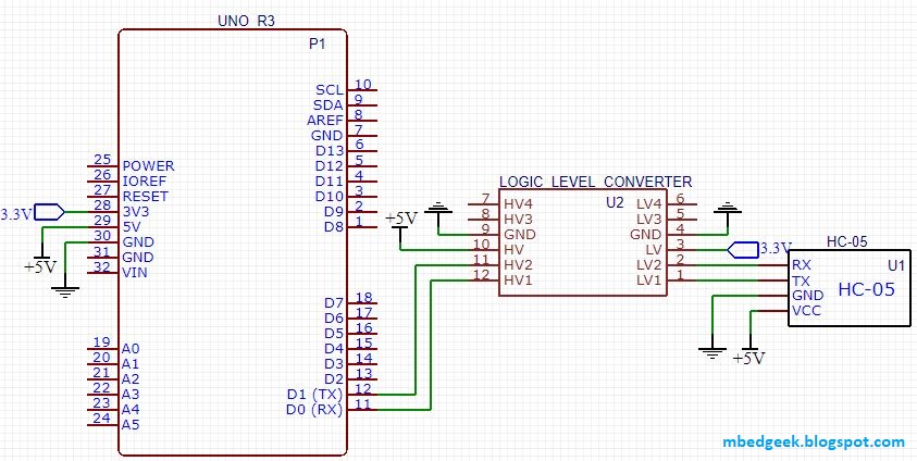
     In this example we will discuss how to interface a Bluetooth module through a Bidirectional level shifter (converter) to an Arduino uno. Arduino uno is a 5V operated device and most of the commonly available Bluetooth modules are 3.3V operated (Serial communication). Though some of the modules will work directly with Arduino, some may not work and some may even get damaged due to 5V signals from Arduino. Also it would be useful to learn how this logic level converter works.


List of components you will need,
  1. Arduino Uno
  2. HC-05 Bluetooth module. (even HC-06 would be fine for this example)
  3. Logic Level converter/Shifter (3.3V to 5V Bidirectional Converter)
  4. Bread Board
  5. Jumper wires
  6. Android mobile phone and a computer
  7. Bluetooth SPP Pro mobile app

Simple Way, Would It Work With Resistor Voltage Dividers?


How to connect Bluetooth modules to Arduino without converters
How to connect Bluetooth modules to Arduino without any converters

As I mentioned earlier 5V logic level can damage Bluetooth modules which are 3.3V in logic level ! Therefore we can use resistor voltage dividers to match the voltage. This will ensure the safety of your Bluetooth module.

Although 2V is considered as the minimum input high voltage in 5V operated devices, still there could be issues with interfacing 3.3V devices with, some of the commercially available 5V devices. Therefore we'll see how to convert both RX and TX of the TTL serial communication. 

(Since speed, size and power has been a consideration over the past years there has been changes in logic levels. And logic level translation using level shifters is a bit more serious topic to speak about.)


Connect Arduino TX (5V) to Bluetooth RX(3.3V) using resistor voltage dividers

How to Connect : The Proper Way

How to connect Bluetooth module using level shifters


How to connect Bluetooth module using level shifters
As shown in the images, the ideal way to interface a 3.3V logic level device with a 5V logic level device is using a level shifter. There are few commercially available devices which are more or less does the same function. But you'll need to be careful when using unidirectional devices rather than the bidirectional devices. Also note that these voltage level shifters support even lower level voltages than 3.3V.
If you do not have 3.3V available to bias the level shifter, (ex: custom made Arduino board with no 3.3V) you can use a resistor voltage divider using 1k and 2k resistors. (which may not be the ideal way, but it works, It is always better to use a LDO (Low Dropout Regulator) regulator like AMS1117-3.3V to create 3.3V)

Lets Code It


/*This Arduino code will read data from arduino serial monitor and print onto the software Serial and vise versa.
  Software serial can be connected to a bluetooth device and can demonstrate a two way communication between the
  mobile phone and arduino using an app like bluetooth spp pro

  Reference : Arduino software serial example

  Coded by : Manjula Karunarathna
  Date : 11th Nov 2018

*/


#include <SoftwareSerial.h>

int rx_pin = 10;                          //defining software serial pins (RX and TX) for arduino uno
int tx_pin = 11;
SoftwareSerial BluetoothSerial(rx_pin, tx_pin);


String HD_Read_String;                   //initialize a string to read data from hardware serial terminal

void setup() {

  Serial.begin(9600);                    // set the data rate for the Hardware Serial port
  Serial.println("Hardware Serial is working !");


  BluetoothSerial.begin(9600);            // set the data rate for the SoftwareSerial port
  BluetoothSerial.println("Software Serial and Bluetooth is working !");

}

void loop() {
  if (BluetoothSerial.available())       //Read from Bluetooth and print onto Hardware Serial
  {
    Serial.write(BluetoothSerial.read());
  }

  while (Serial.available())             //Assign data on hardware serial terminal to a string, run the loop while serial data is available
  {
    delay(1);                              //delay allows byte to arrive in input buffer   
    char c = Serial.read();
    HD_Read_String += c;
  }

  if (HD_Read_String.length() > 0)         //Check whether HD_Read_String was updated
  {
    BluetoothSerial.println(HD_Read_String);

    HD_Read_String = "";                   //reset the HD_Read_String to a null value
  }
/*if you are dealing with only integer values you can use Serial.parseInt() command instead of using a char array which, is much easier */
}
To understand this part of the project you need to have a rough idea on what software serial is. I've used a software serial to interface Bluetooth module and Arduino and the hardware serial port (UART) to communicate between the PC and Arduino. Using this you can send any text between the PC and a mobile phone for both ways.
Android mobile app I've used is "Bluetooth SPP pro" which is pretty decent to such applications. Use the command line mode after pairing and connecting with either HC-05 or HC-06 Bluetooth module. (normally pairing code is either 1234 or 0000)
If you are going to work with only integers or if you are going for an application like output controlling you can even work with "Serial.parseInt()" which is much easier than going for a char array.
Hope this would help to solve your issues on Bluetooth communication.