How to operate relays using Arduino ?


Why we cannot operate relays directly using Arduino or any other microcontroller ?

Lets take a look at what Arduino Uno datasheet says,


Arduino Specifications Datasheet
Arduino Specifications Datasheet (Image Courtesy, farnell.com)

Since Arduino Uno consists with ATmega328P microcontroller, we'll have a look at its data sheet too.
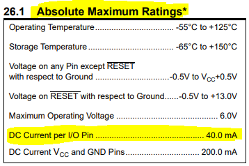

ATmega328P Specifications Datasheet
ATmega328P Specifications Datasheet (Image Courtesy, microchip/atmel)

Also Arduino.cc suggests DC current per I/O pin to be 20mA. So we cannot design anything for 40mA as it is the absolute maximum. Normally a small relay may consume a current starting from 20mA to 60 mA. However even if the current was enough, it can damage the microcontroller due to flyback voltage spikes that comes due to inductive load of the relay. Therefore even if it works, never connect a relay directly with a microcontroller.


Wrong connection of relay with microcontroller
Wrong connection of relay with microcontroller 

So there are few options we can use to connect relays, We'll go through couple of solutions.

Connecting relay using a transistor,


In this method, relay is not electrically isolated from the microcontroller. A freewheeling diode is recommended for the protection of the transistor. Output pin has to be high in order to power the relay coil.

Connecting relay to a microcontroller using a transistor
Connecting relay to a microcontroller using a transistor 

Operate relay using a transistor
Operate relay using a transistor 

Connecting relay using Darlington arrays


In this method also relay is not electrically isolated from the microcontroller. However this will be one of the best option when we have to connect a series of relays for a microcontroller. Since this darlington array I've selected has inbuilt freewheeling diodes, there is no need to add flyback protection for this.


Connecting relay to a microcontroller using a Darlington Array
Connecting relay to a microcontroller using a Darlington Array

Operate relay using a Darlington Array

Connect Relays using Opto-couplers


Even though this circuit is little more expensive than the previous methods, it has a great advantage over previous methods. If your microcontroller circuit is delicate, susceptible to noise or sensitive, optocouplers in this circuit isolates the signal side from relay electrically. (connected optically) 

Lets see how we connect it if we choose to switch the ground connection. In this method output of 0 V will operate the relay. Advantage of this method is that we can choose the supply voltage of the microcontroller/ separate voltage source to operate the relay.

Connecting relay to a microcontroller using Optocouplers, Low Side
Connecting relay to a microcontroller using Opto-couplers, Low Side


Also we can switch the high side of the Opto-coupler where relay will operate when output signal is high. Diagram below highlights the electrical isolation too.
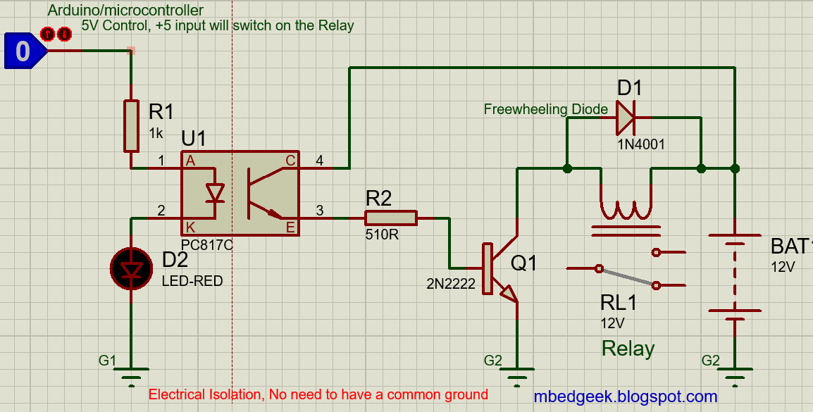

Connecting relay to a microcontroller using Optocouplers, High Side
Connecting relay to a microcontroller using Opto-couplers, High Side

Operate relay using an Opto-Coupler


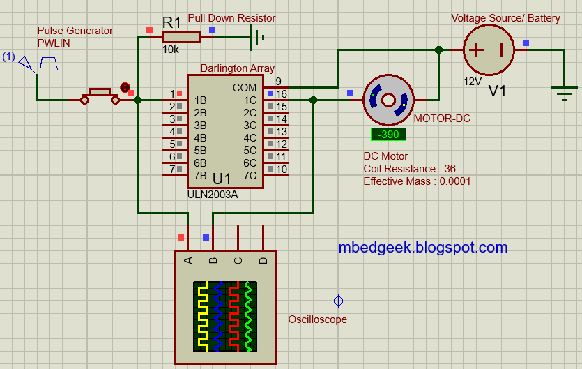
ULN2003A Darlington array Based DC Motor Driver


DC motor control using ULN2003A Darlington Array

In terms of DC motor controlling ULN2003A will not be the great option as it does not support direction change of the motor. However there are few other advantages of the driver.

  • 500mA Rated Collector Current
  • High Voltage Outputs (50V)
  • CMOS, TTL compatibility
  • Inclusion of Suppression Diodes (Easy to drive inductive loads like motors, relays etc)
  • Outputs can be connected in parallel to achieve higher current ratings

Lets see how it reacts on the input states. We'll use Proteus to simulate.

ULN2003A Simulation
ULN2003A Simulation

ULN2003A Simulation Oscilloscope Output


ULN2003A darlington array works like a not gate. Also note that we need to add load in order to simulate the output state.


Now lets see how we can use it as a DC Motor Driver

For this exercise also we can use Proteus to simulate.

ULN2003A DC Motor Control


Output from the Oscilloscope is same as the previous one above. Also note that I had to pulldown the input pin due to Switch resistance, Input impedance and the supply frequency. In practical, it may not be necessary but, better to put a resistor. Also it will even help to reduce noise due to human touch and EMI etc. Addition of a smoothing capacitor for the power source will make it more robust if power source is not a battery.

Most importantly this motor driver is not an ideal solution for many cases as it cannot operate bi-directional. (Cannot change the direction of the motor) So there are better options like L298, L293 etc.

DIY Power Supply from a computer Power Supply


⚠️ Projects like that include mains power may be extremely dangerous. Therefore be cautious while working with mains power.

PSU (Power Supply Unit) is one of the useful part you can reuse from an old PC as a very good power supply alternative.

I found this PSU from my old pc which was in good working condition. 


Power Supply unit from a Scrap Computer
Power Supply Unit from a Scrap Computer

See the specifications below, It has a very good current capacity. 😎
Power Supply Unit Specifications

Voltages generated in the PSU,
  • 12V x 2 
  • 5V
  • 5VSB (5V Standby)
  • 3.3V
  • -12V

Since I need only the 5V and 12V at the moment I am going to use connectors for only these two voltages. 

If opened, it would look like a mess. But all these cables are colour coded and labeled.


Power Supply Unit Inside


Sorted and Labeled Wires PSU
Sorted Wires of 12V, 5V, 3.3V and -12V

PSU Colour Code

  • Yellow : 12V
  • Red : 5V
  • Orange : 3.3V
  • Purple : 5VSB (Standby)
  • Blue : (-12V)
  • Black : Ground
  • Green : PS/ON (Power On)
  • Gray : Power OK


How to switch on the power supply

After giving AC power and switching on the PSU you will have to manually connect the PS/ON (Green) wire to the Ground (Black) wire in order to power on. In this case I am going to use a SPST switch to connect these wires to power on. Also this can be used to check the power supply by switching it on and by measuring the voltages.


PS/ON (Green) Cable
PS/ON (Green) Cable, Connect this with any of the Black wire

Since the casing is metal and I wanted to keep the sockets (4mm female banana) isolated from the casing I've used a piece of plastic to mount them.


Banana Connectors Plastic piece
Metal enclosure was cut using a small cutting tool to fix this plastic piece. Since it was like a net, it took only couple of minutes.

Cutting the PSU Case

Connect those Banana sockets to 12V and 5V wires respectively. Since those wires are about 0.5 sqmm and they cannot carry much current, I've used three wires in parallel for each banana socket from same voltage. (for both positive and negative) Remember it is important to cut the wires into same length in order to avoid over loading of the shorter wires. It would be ideal if we can use fuses for 12V and 5V outputs separately, which I didn't do. 😑 


Connecting Multiples wires PSU
Connecting Multiples wires to increase the current capacity


How to connect wires using heat shrink
How to secure wires using heat shrink

Since this power supply is susceptible to vibration (due to Cooling Fan, AC power supply and Switching of the SMPS) it is important to take counter measures to avoid vibration and fatigue failure. I've used hot glue and cable ties for solder ends and long wires.


Fixed cable ends
Fixed cable ends and long cables

Connect the cooling fan, close the box, and power it, it is now completed


Completed Power Supply Unit

To make it more attractive and convenient we can put the power supply cable on the other side of the front panel.

Astable Multivibrator Using Transistors


This may be the fist step of electronics in the most of the newbies. Though this is a very simple circuit, it takes a little bit of time to understand the working principle of the unit. Lets see how it works.


First we will make the circuit.


Astable Multivibrator


How does it really works,


To understand this circuit it is important to note that both sides of the circuit are not identical. Due to some asymmetry one transistor starts conduction (On State) and the other is not in the beginning. Lets assume that T1 is on and T2 is off. Voltage at the collector of T2 (Vc) is in high state (closer to Vcc) and the Capacitor C2 is charging. Voltage across the capacitor is Vcc on the positive and, 0.7V on the negative side. Once it is charged, it will stop the current flow through the base of T1 transistor which will cause T1 to go to off state. Then Capacitor C1 will have a similar condition like C2 in the previous state and it will start charging. This will cause T2 to go to on state where positive side of the C2 capacitor will be grounded through transistor. C2 starts discharging, but the voltage on the negative side will be on the negative potential until it increases through the discharge cycle up to 0.7V which will cause T1 to go to on state. This cycle repeats. 

In this video, electronsapdotcom explains how it works,


For further studies we can connect an oscilloscope like this, (refer the video for graphs)


Astable Multivibrator with Oscilloscope

Since I wanted to make the On/Off time of the LEDs variable, I've added a variable resistor to the discharging node.


Astable Multivibrator with Variable Speed


Few tips on Proteus in designing the circuit.
  1. Use power and ground from terminal rather than a battery to power the circuit. (Can change the Vcc voltage from (Design >> Configure Power Rails >> Select Vcc/Vdd from "Power Supplies" and put the desired voltage.
  2. Do not use generic components, (ex: use transistors like BC548, 2N2222 etc.)


Here I've added drawings for a PCB for the Transistor Astable multivibrator.


PCB TOP Astable Multivibrator
PCB Top Layer - Astable Multivibrator


PCB BOTTOM Astable Multivibrator
PCB Bottom Layer - Astable Multivibrator


Download the Gerber files from here.
Project file in EasyEDA

PCB Manufacturers (you can easily upload the gerber files to one of these web sites and order)
  1. JLC PCB
  2. SEED STUDIO
  3. PCB WAY

Heart Beat Monitor using Op-Amp

Key Topics : Op-Amp Stethoscope, DIY Stethoscope, Heat Beat Monitor using Op-Amp, Non Inverting Amplifier, Dual Power Supply


We will see how can we make a simple Audio amplifier which can even let us hear own own heartbeat. It is important to know that this is not a power amplifier which can drive large woofers but only a small headphone, This circuit is designed not only to listen to heartbeat only, it can amplify any small sound to a level we can listen through a small speaker/ headphone.

Theory used in this circuit is the famous non inverting amplifier in Op-Amps. 


Non-Inverting Amplifier basics
Lets see the gain calculation,


The use of capacitor is to filter the DC offset and allow only the signal to pass through. Value of the capacitor will depend on the frequency range we are going to use in this application. Also we will be using couple of preset (variable resistors) so that we can change the gain as we need in our application.

This Op-Amp requires a dual power supply. Read this article to find out how to make a dual power supply. Since this requires only few milli amps I've selected the cheapest and easiest way to bias the Op-Amp. (Note that this is not suitable for circuits with higher current requirements)


Simple and cheap dual power supply.
Simple and cheap way to make a dual power supply.

Lets see the Op-Amp circuit,


Op-Amp Stethoscope circuit
Op-Amp Stethoscope circuit 

I've used LM324 Op-Amp as this is a very cheap one and capable of operating in the required voltage range. Condenser microphone is also very cheap and can buy from any electronic component store. I've used an old earphone to observe the sound. Since input side of this circuit is very susceptible to noise, I've soldered this using a perfboard to avoid loose connections compared to a breadboard. 

Op-Amp Stethoscope
Op-Amp Stethoscope

Good Luck 😉