DIY Cheap Real Time Clock using DS1307

Keywords : RTC, Real Time Clock, DS1307, I2C Communication, RTC Library


INTRO : Real Time clocks are very much useful to keep track of time in most of the electronic appliances. Refer the below images for your reference. However if you are designing a circuit, it would important to make a one yourself rather than using a breakout board which would be much expensive and less convenient. Lets see how to get this done.

In this example I've selected DS1307 serial real time clock which actually would cost few cents.

You can download the datasheet from here. DS1307


Highlights DS1307 Datasheet
Highlights from DS1307 Datasheet
Lets see the typical connection of DS1307


DS1307 typical connection Schematic
Notes : In Arduino Uno : Connect SDA Pin to A4 and SCL Pin to A5. Keep the watch crystal as much as closer to the IC oscillator pins (Pin 1 and Pin 2)

DS1307 Arduino Uno Connection Diagram
DS1307 and Arduino Uno Connection Diagram
Required components


  1. DS1307 Integrated IC  (I've selected a DIP version of this)
  2. 32.768 KHz Watch Crystal  (Very cheap and commonly available)
  3. CR2032 Battery and Battery Holder (Can use any other 3V Battery)
  4. 2 x 4.7k resistors (Pull-Up resistors for I2C communication)
  5. Breadboard
  6. Jumper Wires
  7. Arduino Uno (Can use any other microcontroller with I2C, Arduino is much easy)

See How I've Connected the circuit on breadboard,
DS1307 Arduino Circuit
DS1307 Arduino Circuit Assembly
Now we can use I2C Scanner Program to see whether I2C communication is working well. (Skip this if you are confident)


  1. Copy the I2C Scanner Code. (You can find the code from here)
  2. Connect Arduino to the PC
  3. From Tools, Select the Board and Port
  4. Then Upload the I2C Scanner Code 
  5. Open the Serial Monitor (Select Baud rate as 9600)
DS1307 I2C Scanner
DS1307 I2C Scan result


Now Lets download the RTC Library.

1) Go to "Sketch" >> "Include Library" >> "Manage Libraries"


Installing RTC Library
2) Type "DS1307" on the search tab and press "Enter"


Installing RTC Library
3) Find "RTCLib by NeiroN" and Install


Installing RTC Library

Now Lets try the example code

1) Go to "file" >> "examples" >> "RTCLib By NeiroN" >> "rtc_format" and open the code.

RTC Example DS1307
RTC Example Run
2) Go to Tools and select the board and port

3) Upload the code

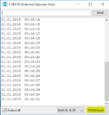
4) Open the Serial Monitor (Do not forget to change the Baud Rate to "57600"

RTC DS1307 Results
RTC DS1307 Results


How to measure distance using Ultrasonic sensor

Keywords : ultrasonic sensor, Arduino, HC-SR04, ultrasonic library, tinkercad

What is ultrasonic distance measuring

Measuring distance using ultrasonic technology is just a one application of ultrasonic technology. (There are other applications like ultrasound scanning, ultrasonic cleaning, ultrasonic polishing etc,)
Ultrasonic sensors are often called as Sonar sensors and we can use them for many applications like,
  • Distance measuring (Robotics applications,Parking applications, Collision detection)
  • Depth and level monitoring (Liquid level monitoring)
  • Object presence detection (Home automation, Automated parking, Security Applications, Light Management Systems etc)

In this article we will see how to use cheap HC-SR04 sensor along with an Arduino to measure distance with an object. It is really important to note that there are various types if ultrasonic sensors which can be used for different applications. Ultrasonic sensors work on the range above the range which human ears can sense.(20 Hz - 20 kHz) The sensor we are going to use ( HC-SR04 ) will work on the range of 40 kHz.

Lets see the working principle of ultrasonic sensor.
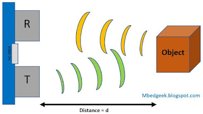
ultrasonic sensor working principle
How Ultrasonic sensor works
 Transmitter part of the sensor send an ultrasonic signal which will bounce back with the obstacles on its way. Receiver detects the echo of the ultrasonic wave and gives us a feedback. Since we can measure the time gap between the trigger signal and echo signal we can measure the distance to the obstacle. (for normal calculations we take the speed of sound in Air as 340 m/s. 

Lets see what its datasheet can offer, HC-SR04 Datasheet

As per the datasheet we can use ultrasonic.h library.

How to download the library.

1) You can download it from here : HC-SR04 Library
(And then unzip and copy it into your Arduino Library folder, ex: C:\Program Files (x86)\Arduino\libraries

2)  Or else you can download the ultrasonic sensor library as below.
go to sketch >> Include Library >> Manage Libraries 
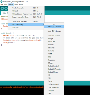
Installing ultrasonic Library - 1

And then, wait few seconds to update the Arduino libraries and type "ultrasonic.h" and press "enter" in the search bar.
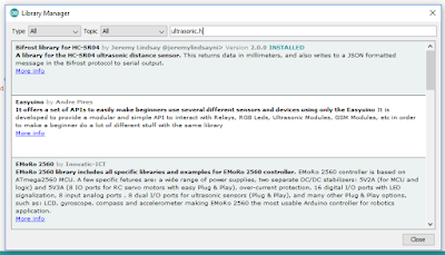
Installing ultrasonic Library - 2

Go down and find the below library and click Install. "Ultrasonic by Erick Simoes"


Installing ultrasonic Library - 3
OK. Now you are good to use ultrasonic library.


Lets connect Arduino Uno with Ultrasonic Sensor
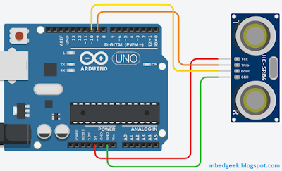
Arduino Uno HC-SR04 connection
Arduino Uno and HC-SR04 connection

<ARDUINO CODE>      //Print distance in cm, using the ultrasonic library
#include <Ultrasonic.h>

const byte trigger_pin = 9;
const byte echo_pin = 10;

Ultrasonic ultrasonic(trigger_pin, echo_pin);  //(initialize the library with connections)

void setup() {
  Serial.begin(9600);
}

void loop() {
  Serial.print("Distance (cm) : ");
  Serial.println(ultrasonic.distanceRead());      //print data in cm
  delay(100);
}
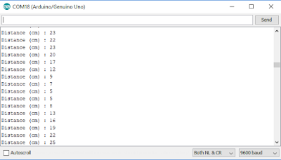
Print Ultrasonic Data in Centimeters

<ARDUINO CODE>         //Print distance in inches, using the ultrasonic library
#include <Ultrasonic.h>

const byte trigger_pin = 9;
const byte echo_pin = 10;

Ultrasonic ultrasonic(trigger_pin, echo_pin);  //(initialize the library with connections)

void setup() {
  Serial.begin(9600);
}

void loop() {
  Serial.print("Distance (inches) : ");
  Serial.println(ultrasonic.distanceRead(INC));      //print data in inches
  delay(100);
}
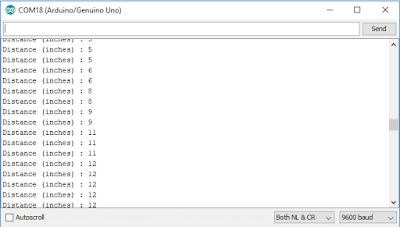
Print Ultrasonic Data in Inches

Ultrasonic sensor can also be easily implemented without ultrasonic.h library. Since ultrasonic library is not available in "tinkercad" I will simulate it using "tinkercad". 


<ARDUINO CODE>  //Print distance in cm, without using the ultrasonic library
const byte trigger_Pin = 9;  //Initialize I/O pins
const byte echo_Pin = 10;

unsigned long duration;  //Since PulseIn return an unsigned Long 
unsigned int distance;  //To save the distance

void setup() {
  Serial.begin(9600);   //Initialize Serial communication
  pinMode(echo_Pin, INPUT);      //Echo pin as Input
  pinMode(trigger_Pin, OUTPUT);   //Trigger pin as Output
}

void loop() {
  digitalWrite(trigger_Pin, LOW); //Make Trigger pin Low at start
  delay(1);
  digitalWrite(trigger_Pin, HIGH);
  delayMicroseconds(10);  //Make Trigger pin High for 10 uS to start sending the pulse
  digitalWrite(trigger_Pin, LOW);

  duration = pulseIn(echo_Pin, HIGH);  //Save the time it took ultrasonic wave to come back
  distance = duration * 0.017; //((340*100)/10e6)/2
/* Speed of the sound in Air = 340 m/S
 * multiply it by 100 to get the data in cm
 * divide by 1,000,000 as duration is measured in microseconds
 * divide by 2 as ultrasound signal travels to object and comes back
 */
  Serial.print("Distance (cm) : ");
  Serial.println(distance);
  delay(100);
}


Data Types in Arduino

Keywords : Data Types, Integers, How to declare Variables in Arduino

What is a Data Type 

A data type can be defined as a classification which describes the value a variable holds and the operations we can perform on it.

Apart from variables, functions also have data types depending on the values they return.


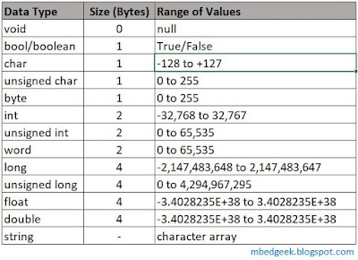
Data Types in Arduino


void

void is only used in Function Declaration. Functions with void return no values when they are called. However they can be used to do some tasks easily. Also it is important to note that Setup and Loop functions are of type void as they do not return any value.


Setup and Loop functions do not return any value


bool/boolean

'bool' is the standard data type defined in Arduino to hold a boolean value (either true or false). in some occasions people use this as 'boolean' also.


Blink Code using boolean type variables

<Arduino Code>
int Led_Pin = 13;       // Uno and Mega has builtin LED on pin 13

bool state = false;           //Boolean value to hold the state of the LED
unsigned long Tracked_Time = 0;   //unsigned long to hold the millis()

void setup()
{
  pinMode(Led_Pin, OUTPUT);     //Declaring Output pin
  Tracked_Time = millis();      //Take the initial value of millis()
}

void loop()
{
  if ((millis() - Tracked_Time) > 1000)   //if time since last change > 1000 ms, delay
  {
    state = !state;     //if true then false, if false then true
    Tracked_Time = millis();      //Saving the time we change the state
    digitalWrite(Led_Pin, state);   //Change the Output state
  }
  delay(5);       //5 ms small delay, will help in Simulations
}

char

Characters are stored in numbers. Therefore it is possible to do arithmetic operations on characters. The value used is the ASCII value of the Characters.


char variable in Arduino


unsigned char / byte

Unsigned char and byte in Arduino is all the same. These can be used to store values from 0 to 255.


unsigned char variable in Arduino
unsigned char variable in Arduino


int (integer)

Integer is the most used data type in Arduino. In ATmega based arduino board (Uno, Mega, Nano etc) 'int' uses 2 byte of memory and as a range of -32,768 to +32,767. But in some advanced boards like Due and MKR1000 int uses 4 bytes from memory and ranges from -2,147,483,648 to +2,147,483,647. 


int variable in Arduino
int variable in Arduino


unsigned int / word

unsigned int and word are very much same as int data type, instead they do not use the negative counter part of the variable. So the range of value becomes from 0 to 65,535. And same as Integer some boards like Arduino Due uses 4 byte of memory and the range becomes from 0 to 4,294,967,295.  


long and unsigned long

Long variables use 4 bytes from memory and unsigned long do not use the negative counterpart, so that positive range becomes larger. (refer Data Types Table for range of values)

It is very important to note use unsigned long variables when working with millis() function as millis() is an unsigned long variable. using other types may cause errors in arithmetic operations.


float and double

In ATmega based boards float and double are all the same. However in some boards like Due double uses 8 byte of memory which gives precision of 64 bit. Mathematical operations with float values are not very efficient in Arduino. Therefore we may have to convert them to integers and do the operations when timing is very critical. 


float and double in Arduino
float and double in Arduino

<Arduino Code>

float F_Number_1 = 22.0;
float F_Number_2 = 7.0;

double D_Number_1 = 22.0;
double D_Number_2 = 7.0;

void setup()
{
  Serial.begin(9600);
}

void loop()
{
  Serial.print(F_Number_1 / F_Number_2, 4); //prints up to four decimal points
  Serial.print("\t");     //prints a Tab
  Serial.println(D_Number_1 / D_Number_2, 4);
  delay(500);
}


Arduino's are much slower in Arithmetic Operations with float variables compared to integer variables. Therefore there are occasions that we may need to even convert the float into integer and do the operations. See the below video to see the speed comparison in arithmetic operations and also serial print.


<Arduino Code>

float num_1 = 21.0;   // Declare Variables
float num_2 = 7.0;
float num_Div = 0.0;

unsigned long Time_Start = 0;
unsigned long Time_Calculated = 0;

void setup()
{
  Serial.begin(9600);
}

void loop()
{
  Time_Start = millis();    //Record Starting Time
  for (int i = 0; i < 1000; i++)    //Do a Small Calculation for 1000 iterations
  {
    num_1 = num_1 + 1.0;
    num_Div = num_1 / num_2;
    Serial.println(num_Div); //Serial Print the value of Calculation, use "Serial.println(num_Div,4);" to print with four decimal points
  }
  Time_Calculated = (millis() - Time_Start);
  Serial.print("Calculated time for Float : ");
  Serial.print(Time_Calculated);      //Print the Calculated time for 1000 iterations
  Serial.println(" mS");

  while(1)      //Stop Serial Print
  {
    
  }
}

string

Strings in Arduino is a long subject to discuss and we'll be discussing it in a separate blog post.


LM2596 Buck Converter Vs LM7805 Linear Voltage Regulator

Keywords : LM7805, LM2596, Linear Regulators, Buck Converters, Switch Mode Power Supply (SMPS)


Recap on 7805 Linear Voltage Regulator


We've had a previous discussion on Linear Voltage Regulators and Linear Drop Out Regulators. You can find the article here. Today we will discuss on the the difference between the 7805 Linear Regulator and the LM2596 Buck Converter.


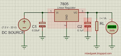
7805 Schematic
IMG 01 : 7805 Schematic


7805 Circuit
IMG 02 : Circuit on a breadboard


LM7805 output from an oscilloscope
IMG 03 : LM7805 output from an oscilloscope

Now lets have a look at the LM2596 based buck converter module and then we'll go for the comparison.


LM2596 Buck Converter Schematic
IMG 04 : LM2596 Buck Converter Schematic


LM2596 Buck Converter Oscilloscope Output
IMG 05 : LM2596 Buck Converter Output from an Oscilloscope


Commercially available LM2596 Converter Module

Now we'll see the comparison between LM7805 and LM2596.


Comparison of Specifications


IMG 06: LM7805 and LM2596 Comparision
LM7805 is a Linear Regulator where LM2596 is a Switch Mode Power Supply (Buck Converter). The biggest disadvantage of LM7805 over LM2596 is the inefficiency. To understand this we'll do a simple calculation. We'll take an application of a 20V input and a 10 Ohms Load resistor.


LM7805 Efficiency Calculation
IMG 06: LM7805 Efficiency Calculation

Then,
Total Power Supplied = 20 V x 0.5 A = 10 Watts  (Resistive Loads)

Resistive Load Power Consumption = 4.98 V x 0.5 A = 2.5 Watts


Efficiency

What happens to the rest of 7.5 Watts ? It is dissipated through the Linear Regulator. So higher the input Voltage and Current higher the power dissipation of regulator. Also, when power dissipation of the regulator increases, efficiency becomes lower. This is the biggest disadvantage of Linear Regulators. We'll be needing bigger heat-sinks when this power dissipation becomes higher. But in the case of Buck converters, they are very efficient and requires very minimum of additional heat sinks. Also when power consumption is critical (ex: battery powered applications) Buck converters would be really handy.


Compactness and Cost

However linear regulators are much more compact and cost effective compared to Buck converters. Therefore they are widely used when efficiency is not a big concern. Also when the input voltage is very close to output voltage we can use linear dropout voltage regulators which may be efficient as much as buck converters due to lower voltage difference from input to output.


Noise handling Capacity


See the Image 03 and Image 05 I've posted above. You will see that there is a small noise (voltage notch)  present in buck converter output. It is said that there could be even higher noise in buck converter and may cause issues for some sensitive micro-controller applications. So in that case Linear Regulator seems to be slightly better.

How to interface multiple switches using one interrupt

Keywords : Arduino Interrupts, Multiple buttons for one interrupt


Problem 

If you have an application where you need more interrupts than available there are couple of options for you.
ex:
  • Pin Change Interrupts
  • A Hardware design using diodes (Suitable for some of the applications)
  • go for a board/micro-controller with higher no of interrupts

In this post we will discuss how to utilize a one interrupt to check multiple inputs using diodes. (here we will interface multiple switches using one interrupt)

Apart from this you may even utilize Analog inputs along with using resistor dividers to obtain the same function. We will be discussing that in another example.


Interfacing multiple switches single Interrupt pin
Interfacing multiple switches to a single Interrupt pin - Schematic

Interfacing multiple switches single Interrupt pin connections
Interfacing multiple switches to a single Interrupt pin - Connections

As per the schematic All the switches and the interrupt pin are pulled down. When a switch is pressed It will bring up the respective pin to +5V. Also it will bring the interrupt pin voltage to the high state. This will happen for each and every switch. When Coding you can check the respective pin attached to the button inside the interrupt.  (ex: Diodes 1N4001-1N4007, 1N4148 etc) Once interrupt pin receive the signal, program will be diverted to the interrupt function.

Note : If your application is good enough with Internal Pull-up resistors you can do it that way. In that case you the diodes other way round and you will need to change the interrupt mode. (LOW, FALLING etc) 

Simulation


<Arduino Code>
const byte BlinkLED = A0;   //To represent main task

const byte LED_Red = A1;      //Each LED to represent push buttons
const byte LED_Green = A2;
const byte LED_Blue = A3;

const byte Button_Red = 8;      //Initialize pins connected to P/Bs
const byte Button_Green = 9;
const byte Button_Blue = 10;

const byte interruptPin = 2;      //Interrupt pin

void setup() {
  pinMode(LED_Red, OUTPUT); //Declaring Outputs, No need to declare inputs
  pinMode(LED_Green, OUTPUT);
  pinMode(LED_Blue, OUTPUT);

  pinMode(interruptPin, INPUT);   //Define Interrupt Pin as input, since pulled down, do not use INPUT_PULLUP
  attachInterrupt(digitalPinToInterrupt(interruptPin), ButtonPress, HIGH);
}

void loop() {
  digitalWrite(BlinkLED, HIGH);       //What ever the task of the Arduino, in this example its Blinking LED on pin A0
  delay(1000);
  digitalWrite(BlinkLED, LOW);
  delay(1000);
}

void ButtonPress() {
  if (digitalRead(Button_Red) == HIGH) //Check the button Status
  {
    digitalWrite(LED_Red, HIGH);      //Make the respective LED pin HIGH
    while (digitalRead(Button_Red) == HIGH);    //And hold until Button is pressed, may not need such step if your application is different
  }
  if (digitalRead(Button_Green) == HIGH)
  {
    digitalWrite(LED_Green, HIGH);
    while (digitalRead(Button_Green) == HIGH);
  }
  if (digitalRead(Button_Blue) == HIGH)
  {
    digitalWrite(LED_Blue, HIGH);
    while (digitalRead(Button_Blue) == HIGH);
  }

  digitalWrite(LED_Red, LOW); //Make the inputs low again
  digitalWrite(LED_Green, LOW);
  digitalWrite(LED_Blue, LOW);
}

Note : Select the interrupt mode depending on your application. Since I selected to be inside the interrupt during the button press, I used "HIGH". Also it depends on how you bias the pins also. (ex: Pull-up, Pull-Down and diode polarity etc)

What is I2C (Inter Integrated Circuit) Communication and I2C Scanner

Key Topics : What is I2C, I2C Scanner, Arduino Wire, TWI


Before going into I2C Scanner, Lets have a some understanding of what I2C communication is. 


I2C communication is a very easy to use synchronous serial communication protocol. It supports multiple masters and multiple slaves with only two wires ! Also important to note that we can connect any number of masters and up to 1008 slave devices to an I2C network. (But in our case, since we use 7 Bit addresses we can theoretically put only 127 slaves, that also may come down depending on the capacitance on the I2C Bus.) Compared to SPI (Serial Peripheral Interface), it has a lower data transfer rate. Pull up resistors are required when you connect more than two devices to the network. I2C bus drives can pull signal lines to ground but they are not capable of driving it to high. Therefore Pull Up resistors are vital. General rule of thumb is to start from 4.7k Ohms resistors and bring it down depending on the length and the connected devices of the system. When using the wire library (for I2C in Arduino) it activates internal pull-up resistors (20k-150k, depending on the pin and the board model) and Mega 2560 board has on board pull up resistors (10k). 


I2C network
An I2C network


I2C, TWI and WIRE


Since I2C is a trademark for Phillips Atmel and other companies created an identical system called TWI (Two Wire Interface) which is very much identical to I2C. In Arduino Wire library is used communicate with I2C/TWI communication devices. Some of the commonly available I2C devices are listed below. 


RTC, Real Time Clock - I2C
Real Time Clock


AD-DA Module
AD-DA Module


I2C OLED
I2C OLED


I2C LCD module
I2C LCD module


MCP4725 I2C DAC
MCP4725 I2C DAC


What are the dedicated I2C pins in Arduino Boards


I2C pins in Arduino Uno
I2C connection pins in Arduino Uno


I2C pins in different Arduiono Boards
I2C pins in different Arduino Boards

It is important to have an idea about interfacing devices using I2C with different TTL logic levels.(3.3V and 5V) You can get a clear idea from here.


I2C Scanner


In most of the cases we see that people copy Arduino codes from internet and often say their codes are not working. Often manufacturers provide contingencies to change I2C adresses by doing minor hardware changes. (ex : removing/ adding resistors) When devices with I2C communication, first of all we need to check the I2C addresses of the devices. You can find the source code for I2C Scanner from official Arduino site.  (https://playground.arduino.cc/Main/I2cScanner)  


// This sketch tests the standard 7-bit addresses
// Devices with higher bit address might not be seen properly.

 
#include <Wire.h>
 
 
void setup()
{
  Wire.begin();
 
  Serial.begin(9600);
  while (!Serial);             // Leonardo: wait for serial monitor
  Serial.println("\nI2C Scanner");
}
 
 
void loop()
{
  byte error, address;
  int nDevices;
 
  Serial.println("Scanning...");
 
  nDevices = 0;
  for(address = 1; address < 127; address++ )
  {
    // The i2c_scanner uses the return value of
    // the Write.endTransmisstion to see if
    // a device did acknowledge to the address.
    Wire.beginTransmission(address);
    error = Wire.endTransmission();
 
    if (error == 0)
    {
      Serial.print("I2C device found at address 0x");
      if (address<16)
        Serial.print("0");
      Serial.print(address,HEX);
      Serial.println("  !");
 
      nDevices++;
    }
    else if (error==4)
    {
      Serial.print("Unknown error at address 0x");
      if (address<16)
        Serial.print("0");
      Serial.println(address,HEX);
    }    
  }
  if (nDevices == 0)
    Serial.println("No I2C devices found\n");
  else
    Serial.println("done\n");
 
  delay(5000);           // wait 5 seconds for next scan
}
//Courtesy - arduino.cc

Here in this example we'll do the I2C Scanning for DS3231 based RTC (Real Time Clock)


I2C Scanner for RTC Schematic


I2C Scanner for RTC Connections

for this example there is no need to add pull-up resistors. After Uploading the code, open Serial Monitor. (Tools >> Serial Monitor) You'll get a message as follows. 


I2C Scanner Output
Since this version of Real Time Clock (RTC) has an additional eeprom (AT24C32) it shows two I2C Addresses. 
  • 0x57 - AT24C32 EEPROM
  • 0x68 - DS3231 RTC

However if you do not get the above results check the following,

  • GND and Vcc Connevtion for your I2C device.
  • SCL and SDA Connections Between Arduino and device.
  • Baud-rate in code and serial monitor (9600 in this example)
  • If you have more than one device you may need to add pull-up resistors.
  • Sometimes your SCL and SDA cables may be too lengthy.
  • Voltage level of the device (Some devices are 3.3V operated, I've posted a link above which explains how work with level shifters)
  • This program supports only for devices with 7-bit addresses. Check your datasheet.