DIY Power Supply from a computer Power Supply


⚠️ Projects like that include mains power may be extremely dangerous. Therefore be cautious while working with mains power.

PSU (Power Supply Unit) is one of the useful part you can reuse from an old PC as a very good power supply alternative.

I found this PSU from my old pc which was in good working condition. 


Power Supply unit from a Scrap Computer
Power Supply Unit from a Scrap Computer

See the specifications below, It has a very good current capacity. 😎
Power Supply Unit Specifications

Voltages generated in the PSU,
  • 12V x 2 
  • 5V
  • 5VSB (5V Standby)
  • 3.3V
  • -12V

Since I need only the 5V and 12V at the moment I am going to use connectors for only these two voltages. 

If opened, it would look like a mess. But all these cables are colour coded and labeled.


Power Supply Unit Inside


Sorted and Labeled Wires PSU
Sorted Wires of 12V, 5V, 3.3V and -12V

PSU Colour Code

  • Yellow : 12V
  • Red : 5V
  • Orange : 3.3V
  • Purple : 5VSB (Standby)
  • Blue : (-12V)
  • Black : Ground
  • Green : PS/ON (Power On)
  • Gray : Power OK


How to switch on the power supply

After giving AC power and switching on the PSU you will have to manually connect the PS/ON (Green) wire to the Ground (Black) wire in order to power on. In this case I am going to use a SPST switch to connect these wires to power on. Also this can be used to check the power supply by switching it on and by measuring the voltages.
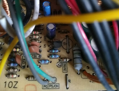

PS/ON (Green) Cable
PS/ON (Green) Cable, Connect this with any of the Black wire

Since the casing is metal and I wanted to keep the sockets (4mm female banana) isolated from the casing I've used a piece of plastic to mount them.


Banana Connectors Plastic piece
Metal enclosure was cut using a small cutting tool to fix this plastic piece. Since it was like a net, it took only couple of minutes.

Cutting the PSU Case

Connect those Banana sockets to 12V and 5V wires respectively. Since those wires are about 0.5 sqmm and they cannot carry much current, I've used three wires in parallel for each banana socket from same voltage. (for both positive and negative) Remember it is important to cut the wires into same length in order to avoid over loading of the shorter wires. It would be ideal if we can use fuses for 12V and 5V outputs separately, which I didn't do. 😑 


Connecting Multiples wires PSU
Connecting Multiples wires to increase the current capacity


How to connect wires using heat shrink
How to secure wires using heat shrink

Since this power supply is susceptible to vibration (due to Cooling Fan, AC power supply and Switching of the SMPS) it is important to take counter measures to avoid vibration and fatigue failure. I've used hot glue and cable ties for solder ends and long wires.


Fixed cable ends
Fixed cable ends and long cables

Connect the cooling fan, close the box, and power it, it is now completed


Completed Power Supply Unit

To make it more attractive and convenient we can put the power supply cable on the other side of the front panel.

Astable Multivibrator Using Transistors


This may be the fist step of electronics in the most of the newbies. Though this is a very simple circuit, it takes a little bit of time to understand the working principle of the unit. Lets see how it works.


First we will make the circuit.


Astable Multivibrator


How does it really works,


To understand this circuit it is important to note that both sides of the circuit are not identical. Due to some asymmetry one transistor starts conduction (On State) and the other is not in the beginning. Lets assume that T1 is on and T2 is off. Voltage at the collector of T2 (Vc) is in high state (closer to Vcc) and the Capacitor C2 is charging. Voltage across the capacitor is Vcc on the positive and, 0.7V on the negative side. Once it is charged, it will stop the current flow through the base of T1 transistor which will cause T1 to go to off state. Then Capacitor C1 will have a similar condition like C2 in the previous state and it will start charging. This will cause T2 to go to on state where positive side of the C2 capacitor will be grounded through transistor. C2 starts discharging, but the voltage on the negative side will be on the negative potential until it increases through the discharge cycle up to 0.7V which will cause T1 to go to on state. This cycle repeats. 

In this video, electronsapdotcom explains how it works,


For further studies we can connect an oscilloscope like this, (refer the video for graphs)


Astable Multivibrator with Oscilloscope

Since I wanted to make the On/Off time of the LEDs variable, I've added a variable resistor to the discharging node.


Astable Multivibrator with Variable Speed


Few tips on Proteus in designing the circuit.
  1. Use power and ground from terminal rather than a battery to power the circuit. (Can change the Vcc voltage from (Design >> Configure Power Rails >> Select Vcc/Vdd from "Power Supplies" and put the desired voltage.
  2. Do not use generic components, (ex: use transistors like BC548, 2N2222 etc.)


Here I've added drawings for a PCB for the Transistor Astable multivibrator.


PCB TOP Astable Multivibrator
PCB Top Layer - Astable Multivibrator


PCB BOTTOM Astable Multivibrator
PCB Bottom Layer - Astable Multivibrator


Download the Gerber files from here.
Project file in EasyEDA

PCB Manufacturers (you can easily upload the gerber files to one of these web sites and order)
  1. JLC PCB
  2. SEED STUDIO
  3. PCB WAY