Heart Beat Monitor using Op-Amp

Key Topics : Op-Amp Stethoscope, DIY Stethoscope, Heat Beat Monitor using Op-Amp, Non Inverting Amplifier, Dual Power Supply


We will see how can we make a simple Audio amplifier which can even let us hear own own heartbeat. It is important to know that this is not a power amplifier which can drive large woofers but only a small headphone, This circuit is designed not only to listen to heartbeat only, it can amplify any small sound to a level we can listen through a small speaker/ headphone.

Theory used in this circuit is the famous non inverting amplifier in Op-Amps. 


Non-Inverting Amplifier basics
Lets see the gain calculation,


The use of capacitor is to filter the DC offset and allow only the signal to pass through. Value of the capacitor will depend on the frequency range we are going to use in this application. Also we will be using couple of preset (variable resistors) so that we can change the gain as we need in our application.

This Op-Amp requires a dual power supply. Read this article to find out how to make a dual power supply. Since this requires only few milli amps I've selected the cheapest and easiest way to bias the Op-Amp. (Note that this is not suitable for circuits with higher current requirements)


Simple and cheap dual power supply.
Simple and cheap way to make a dual power supply.

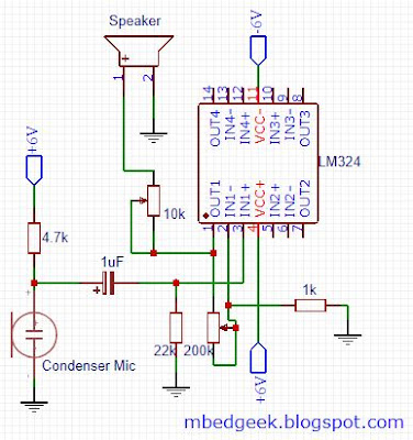
Lets see the Op-Amp circuit,


Op-Amp Stethoscope circuit
Op-Amp Stethoscope circuit 

I've used LM324 Op-Amp as this is a very cheap one and capable of operating in the required voltage range. Condenser microphone is also very cheap and can buy from any electronic component store. I've used an old earphone to observe the sound. Since input side of this circuit is very susceptible to noise, I've soldered this using a perfboard to avoid loose connections compared to a breadboard. 

Op-Amp Stethoscope
Op-Amp Stethoscope

Good Luck πŸ˜‰

How to make a Dual Power Supply

Key topics : Dual Power Supply uses, Dual power supply using two batteries, Dual power supply using two Linear regulators, Dual power supply using resistor dividers

Uses of Dual Power Supply


Most of the Op-Amp applications require dual power supply due to oscillation around ground. Also they are designed to work with dual power rails. Therefore it is important to provide dual power supplies. Also audio applications like power amplifiers, pre-amplifiers, audio applications with vacuum tubes etc require dual power supplies to work.

Lets see some basic circuits we can used to obtain dual power supplies.


1) Dual power supply using two batteries


Dual Power Supply using two Batteries
This may be one of the easiest way to get a dual power supply with a high current requirement. Voltages of the system changes with the batteries used and the current it can cater depends on the batteries used. in high current applications internal resistance of the batteries will have an impact on the output. This is a very efficient but expensive way to get a dual power supply. This is very popular to get +9 V and -9 V dual power supplies due to availability of cheap 9 V batteries. 


2) Dual power supply using two Linear regulators


Dual power supply using Linear regulators
Dual power supply using two Linear regulators

This is one of the famous method to obtain a accurate dual power supply using a center tap transformer, full wave bridge rectifier and linear regulators. It is recommended to add two small capacitors on the outputs of the linear regulators depending on the regulator used. Disadvantages of this are, low current capability ( around 1A in 78XX series, which depends on manufacturer, heat sinks, temperature etc) and inefficiency. Read this article to find more about linear regulators. Also see this article to understand the inefficiency of linear regulators. Output voltage of this depends on the linear regulator used. (ex : 7805 & 7905 for 5V power supply, 7815 & 7915 for 15V power supply etc). Also it is important to use a transformer which provides at least 3V higher than what is required in order to cater the voltage drops at linear regulators and diode bridge. However if the voltage difference is too high it will cause too much inefficiency through the linear regulators also.


3) Dual power supply using resistor dividers


Dual power supply using resistor voltage dividers


This simple and cheap arrangement can be used to cheat😏 circuits with small current requirements. (ex: Op-Amp circuits) Since the potential of the GND depends on the voltage divider created using resistors and capacitors (equivalent series resistance) this cannot be used for circuits with higher current requirements. However if the load is balanced around the +V and -V with reference to the ground this can be used. It is really important to choose the resistors with higher wattage as shown in the diagram. 


Design power supply for SIM800L Core Board


Key topics : Powering SIM800L Module, SIM800L Core Board, Linear Regulator, Buck Converter, SMPS, Arduino

Introduction

As it seems most of the issues related to SIM800L core board is due to inappropriate power supply. If you want refer this SIM800L hardware design where manufacturer clearly specifies the suitable power supply for SIM800L module. 

Refer the power supply specifications 


  • Voltage : 3.4 V to 4.4 V (4.0 V recommended, Some of the latest versions may work directly with 5V power supply)
  • Current Rating : 2 A (To cater the demand at transmit bursts)

If you provide this voltage and observe the current through the Ammeter you will hardly notice a current of 2 A but few milli Amps. It will be using 2A at transmit bursts for less than a milli second at a time. Therefore it is really important to provide a power supply which can provide 2A with a very minimum voltage drop.

Most of the time issues related to power supply is because of people using linear regulators which cannot supply adequate power as well as not the suitable voltage. (Even in Arduino boards 5V power supply cannot provide more than 500 mA and 3.3V Power supply cannot provide more than 100 mA, Also they are not in the range of required voltage level) So directly connecting SIM800L module with Arduino will never fulfill the requirements. 

We'll see what data sheet recommends to power SIM800L module,

Manufacturer recommends to have the following arrangement as much as closer to the Vin pin of the SIM800L module. 


SIM800L Power Input
SIM800L Power Input
If you observe closely you can see that some of those capacitors are already included in the core board. However importance of those components are that,

  • Zenor diode will be removing any voltage sure if present protecting the sensitive electronics
  • 33pF and 10pF capacitors will remove any high frequency interferences
  • 100uF and 1uF are also useful to make the input power supply smooth as well as to help with high current bursts during transmits. Also it is much more effective to use Tantalum capacitors due to low ESR (Equivalent Series Resistance) 


Since we cannot work with any of the commonly available power supplies or Arduino power outputs we'll see what are the other options we can have.

1) If you are using a 5 V Power supply manufacturer recommends to use a LDO (Linear Drop-Out) regulator which would be a great and efficient solution in such case. Here in this case they've recommended MIC29302A which can supply up to 3A with a 1% tolerance. 


MIC29302 Power Supply SIM800L
MIC29302 Power Supply for SIM800L

Lets see the output voltage it is designed,


Voltage Calculation MIC29302 SIM800L


2) Since this seems little bit complicated we can easily achieve the same performance by using a diode with a forward bias voltage drop of 0.7V and a rating of 2A. (Consider forward bias voltage when selecting the diode)


Diode Power Supply SIM800L

3) If you are using a power supply above 5V using an LDO or another type of linear regulator would be very much inefficient. So the best option becomes using a Buck Converter (Switch Mode Power Supply) For such applications LM2596 based buck converters would be the ideal solution which is commonly available as well as less expensive.


LM2596 Adjustable Buck Converter Schematic

This is the schematic of most commonly available. Below image shows a commonly available commercial solution of this circuit.

Commercially available LM2596 Converter Module
However if you refer the above datasheet of SIM800L module, manufacturer recommends a slightly different setup with addition of another inductor and couple of capacitors which would deplete the amount of noise this produces. Normally buck converters tends to have a little bit high amount of noises compared to linear regulators. But this works fine with SIM800L module. Even though it is better to add a 100uF capacitor and a 100nF capacitor closer to the SIM800L module when using this.

4) Since most of the Li-Ion Cells are of 3.7 V -v4.2 V and it is in the recommended range we can directly use a Li-Ion cell to power up a SIM800L Module. However be careful when using small batteries as they may not be able to provide the adequate voltage at 2A current burst due to internal resistance. 


Arduino Analog Inputs, PWM Outputs

Keywords : Arduino Analog Inputs, ADC, Analog to Digital Conversion, Minimum Voltage, Analog Output, PWM Output, PWM, Pulse Width Modulation

Arduino Analog Inputs

Almost all the things around us are analogous. Therefore to analyze and understand them in digital world, we need to convert them into digital signals. In Arduino there are inbuilt ADCs. (Analog to Digital Conversions) In Arduino uno there are 06 no of 10-bit Analog inputs available. Some micro-controllers support 8-bit and some even support 12-bit ADC.


What is the resolution


Lets take an Arduino Uno (10-bit ADC). It can show 210 no of different values. (1024 Values, from 0 to 1023)


ADC minimum Value Calculation


To see an application, refer Arduino ReadAnalogVoltage Example
Arduino IDE >> File >> Examples >> 01.Basics >> ReadAnalogVoltage 


Lets get to the example


ADC read using Serial Communication
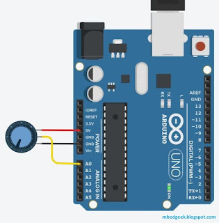
Connections for ADC read using Serial Communication

To access the code, go to,
Arduino IDE >> File >> Examples >> 01.Basics >> AnalogReadSerial 

I've used tinkercad to simulate the result and see how value changed when I rotate the potentiometer.

Also delay after the ADC read was added to slow down the reading and show you how it changed. You may not need to add it.


 Analog Read Serial Simulation
ADC - AnalogReadSerial Simulation


Arduino PWM (Pulse Width Modulation) Outputs

Arduino boards are not capable of providing analog outputs. (We'll discuss how to get analog outputs using DAC-Digital to Analog converter modules) But there are occasions that we can utilize PWM outputs to some of the applications. (ex: LED dimming) Also PWM signals are very much important in DC motor speed controlling and RC Servo position controlling and generation Audio signals. Also using filters we can make analog signals.(hard to create pure analog signals)


ADC read and PWM out
Read Analog from A0 and Write to Pin 09 PWM


 int ledOut = 9;           //You can select only PWM Pins
int BrightnessValue = 0; //Assign PWM value to control Brightness

void setup() {
  pinMode(ledOut, OUTPUT);  
}

// the loop routine runs over and over again forever:
void loop() {
  int AnalogReadValue = analogRead(A0);  //Read the analog value from POT
  BrightnessValue = map(AnalogReadValue, 0, 1023, 0, 255);
  /*Mapping 10-bit ADC value into 8-bit PWM value through map function*/
  analogWrite(ledOut, BrightnessValue);  //Write the PWM Value
}


What is this Boot Loader, How to Burn an Arduino Boot-loader

Keywords : Bootloader, Arduino Bootloader, How to burn Arduino Bootloader

Arduino Bootloader

In general bootloader is a firmware used in micro-controllers. The bootloader may exist in the same memory space where user program exists. When power up or reset, bootloader runs ahead of the main code and it may setup the microcontroller state or even update the main program.One of the biggest application of bootloader is they allow firmware update without dedicated programmers over USART, I2C, SPI or even Ethernet.

The specialty of Arduino bootloader is that it supports reprogramming the available memory space (apart from the bootloader) using serial communication. (Only on serial based Arduino) Without this we’ll be needing a dedicated programmer for the micro-controller.

During power-up Arduino bootloader checks the incoming from UART pins of the microcontroller. If predefined sequence is received, it acts as a programmer, or else it will jump to the user code for the execution. Also, it is important to know that this will happen during the startup of the microcontroller (while executing the bootloader program) which avoids corrupting the flash memory.


How to burn Arduino bootloader to an ATmega328P microcontroller

Lets say you bought an ATmega328P microcontroller to replace a burnt one in your Arduino Uno or you are going to make a custom uno board for your requirements. Sometimes you may get an Atmel chip without bootloader. (note that most of the agents/shops sell both with and without bootloader)
Also the one with boot loader is little expensive than the one without, you may have to go for the first option if you are going to buy a large number of MCUs.

Burning the boot loader into your new MCU is not a very big deal with Arduino as you will not need a dedicated programmer even for that ! All you will need is an uno board, breadboard and some jumper wires.


Lets burn the Bootloader πŸ˜€

1) To do this you need another working Arduino Board with ATmega328P. Connect the Arduino board to a PC and,
i) File >> Example >> 11.ArduinoISP >> ArduinoISP
ii) Select your board type from Tools >> Board  >> Arduino/Genuino Uno
iii) and then Select the Port from Tools >> Port >> Serial Port Arduino has Connected
iv) Select the programmer from Tools >> Programmer >> AVRISP mkII
v) Upload the code
Select Arduino as ISP


2) Disconnect Arduino from PC and connect the ATmega328P (with no boot loader) and the components as below using a bread board. (If need there is a good description in ArduinoISP sketch as comments)


Burning Bootloader Schematic

If you have an additional Arduino board and feel like not using a breadboard, below schematic is for you. connect the two Arduino boards as below. (One with the bootloader on left) I've not marked the status LEDs which are not compulsory. 


Burn Bootloader using two Arduino Boards

3) Now lets connect the one with the bootloader to PC and, go to, 
 Tools >> Programmer >> Arduino as ISP   (You will have to undo this setting after burning the bootloader) 


Burning the Arduino Bootloader
4) Select "Arduino/ Genuino Uno" from Board and the port your Arduino is connected, Then select, 
Tools >> Burn Bootloader


Burning Arduino Bootloader
Burning the Bootloader
That's it πŸ’ͺ